Visualizing Geometry in Hypar
Hypar is one of the new(er) kids in the AEC startup space, so I've spent a bit of my free time exploring its capabilities through the lens of structural engineering in the last few weeks. I've been working on adapting some of the gusset plate design I've previously done, starting with 3d gusset visualization. For some context as to why I would choose this particular structural problem:
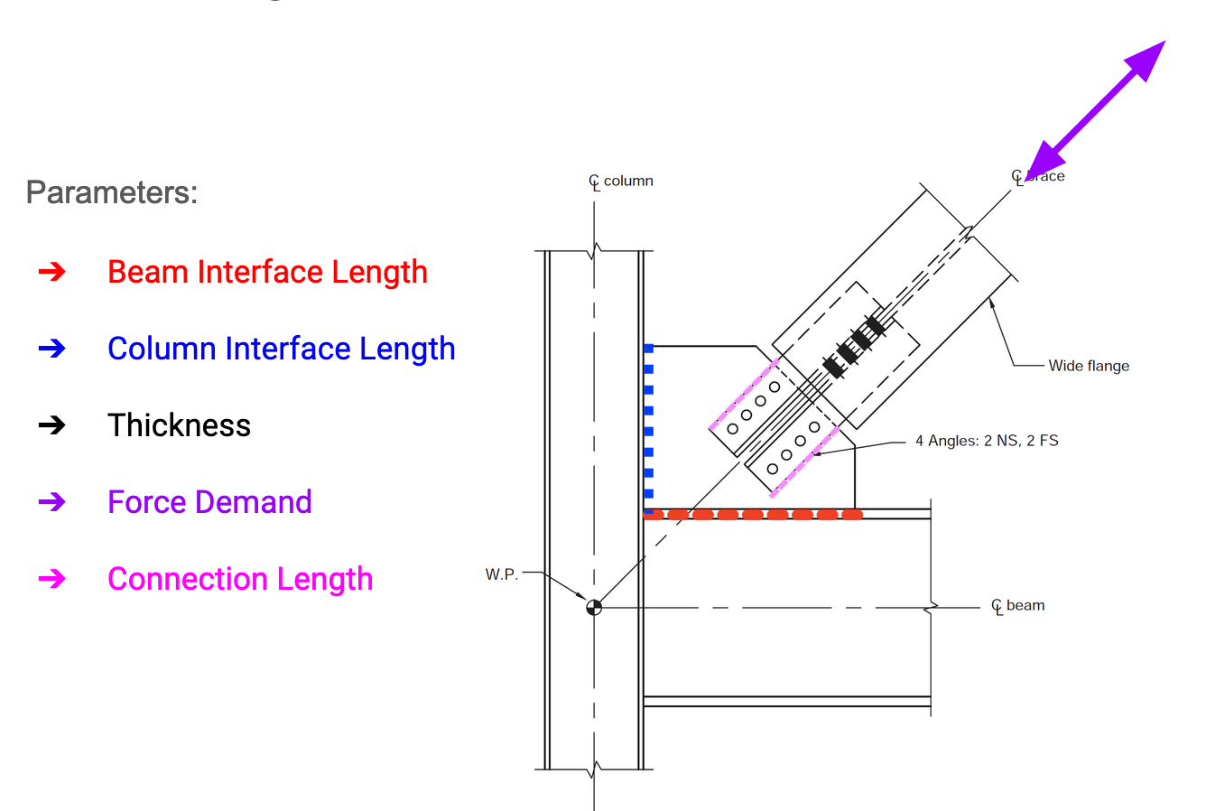
A little over a year ago, I threw together a web application to explore gusset plate design during my time at the Recurse Center. As an engineer, I've spent a lot of time thinking about gusset plates from working on several steel buildings in seismic areas. Gusset plates are the steel plates used to connect diagonal steel elements (braces) to the beams and columns of a building. You'll also see them in truss bridges. Gussets are integral to the load paths in trusses (how the forces get to the ground), and gusset plate failure due to an underdesigned plate was the direct cause of the I-35 bridge collapse back in 2007.
I had previously fixed several convoluted grasshopper scripts to generate "optimized" gusset geometry for a project with a couple hundred steel connections. I say "optimized" because we really only considered the steel weight used, and the process was manual, adjusting thicknesses and dimensions until all the excel cells for design checks popped up as green before moving on to another one. We never investigated anything like limiting plate thickness or packing the geometry to a specific sheet to reduce waste, it was just more of an exercise to get something that somewhat reduced steel tonnage by not rounding off the corners, and it also looked nice in Revit.
For the webapp I designed, I wanted to make an interactive app to explore the design space based on the geometry. This meant playing around with different UI elements to allow someone to alter the geometry and see how it impacted the design checks.
For taking this to something like Hypar, I would want to automatically make those design choices based on a few constraints, but the first thing I wanted to play around with was visualization. Using Dash and Plotly for my webapp presented a lot of challenges for manipulating the geometry in 3d. I didn't really have to worry about gimbal lock for the simple series of rotations I needed to do, but rotating all the elements to the proper position was not easy, and ended up being pretty hacky on my end (I was building all the elements from scratch).
Fortunately Hypar's elements library is one of the open source aspects of the platform, so I could just draw on existing element types for W sections to render my beam/column/brace node, and even offset them the proper amount based on a beam framing into a column. I used my old python script to generate the points for the gusset for this test, because it will take some time to translate to my C# function in Python since each gusset point is generated from intersections of the guide lines.
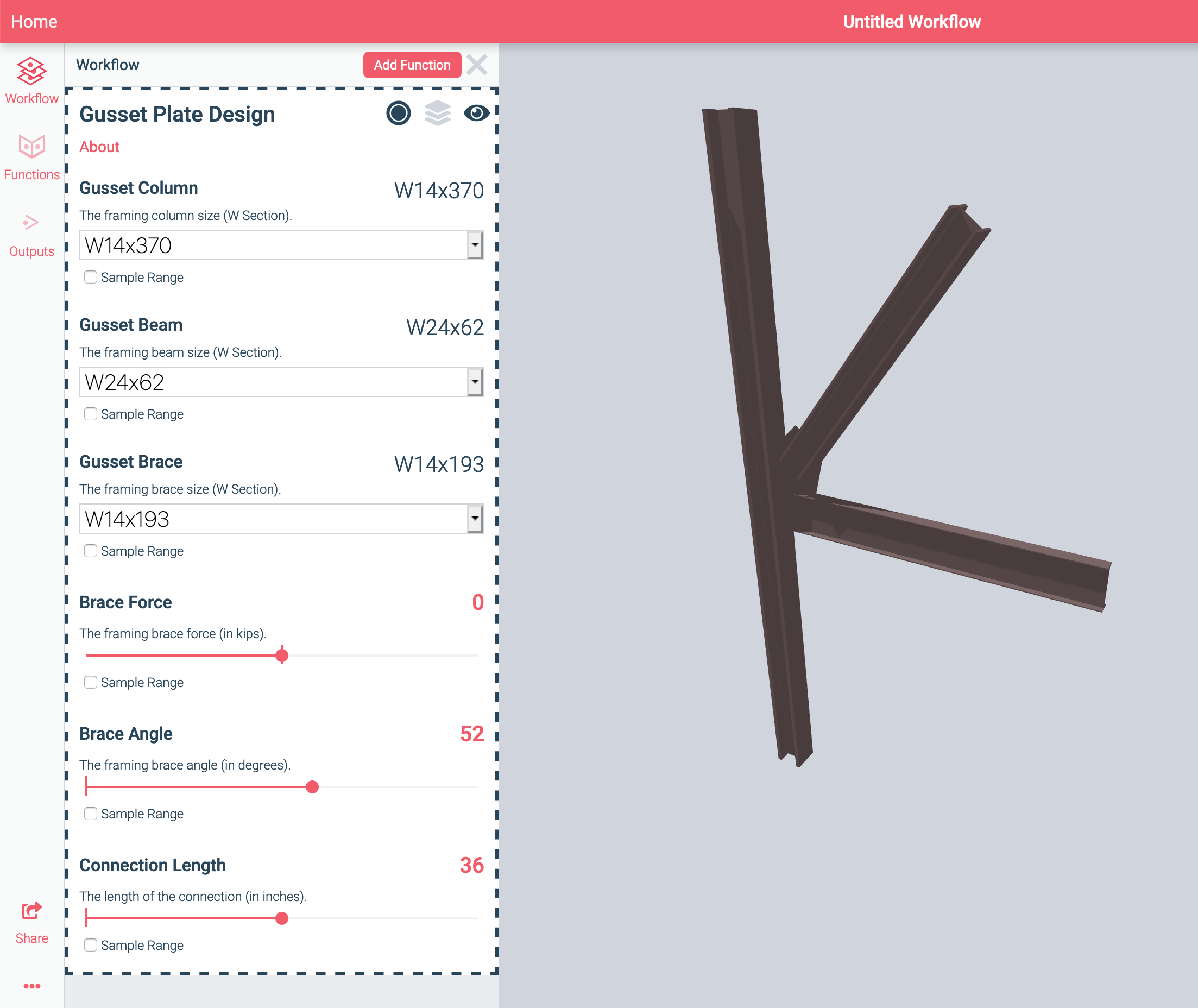
I used a mass element for my gusset, which was automatically created in the XY plane and extruded in Z. To get it to the right spot in the visualization, I had to apply a series of transforms to the geometry, which was still less painful than what I was doing in Plotly. The next steps for this will take quite a bit of code refactoring to take the process from an exploratory interface to an optimization problem.